Potential dividers
Potential dividers are useful but to explain them let us start with electric current. The current carries energy from the energy source (e.g. the battery or the generator) around the circuit. The current does not get used up it simply goes around and around. That is just like water in a central heating system carrying heat from the boiler and flowing back cold and then picking up more energy.


A voltmeter measures the change of energy of the electric current between one place and another, just as we might measure the change in temperature as water enters and leaves the radiator.
The potential difference or voltage we measure is the number of joules of energy transferred to the bulb, in the diagram above, by every coulomb of electricity.
If we had two radiators attached to our boiler, then the energy would be shared between them. The total energy is the same, it has just been divided into two parts.
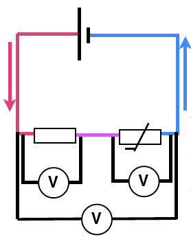
Then, in a similar way, the energy of the electric current is divided by two resistors. The energy delivered is measured by the potential difference, hence the two resistors are a potential divider.


Using a potential divider
The total potential difference / voltage is split into two parts. If the resistors are identical then each will have exactly half of the potential difference.

If the resistors are different the total PD is split in the ratio of the values of the resistors. For example if the total PD is 12 volts and the resistors are 5KΩ and 1KΩ, then the split will be:

Because one resistor is five times as big as the other the voltage across it will also be five times as big. The equation which we can use when the figures are harder to calculate than this is:
R1/R2 = V1/V2
In words, the ratio of the potentials is equal to the ratio of the resistances. This is a useful idea in practical measuring circuits. It makes it easier to measure a change in the potential difference.
Giving a bit more explanation, because the same current flows through both resistors.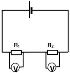
I =V1/R1 = V2/R2
and because V1/R1 = V2/R2 then rearranging this: V1/V2 = R1/R2 so the ratio of the resistances is the same as the ratio of the voltages.
For example a temperature change changes the resistance of a thermistor but the potential difference (voltage) across the thermistor in the circuit below would stay the same. The (tiny) current would alter but this is quite hard to measure.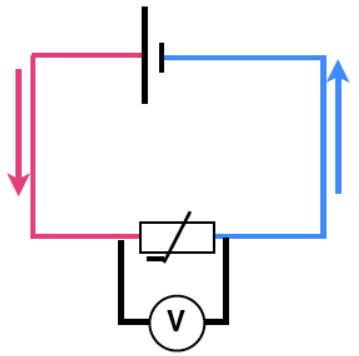
In this circuit below a change in the resistance of the thermistor would alter the balance of voltages measured and these values would be much easier and therefore more accurate, to measure.